


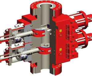
U-Shaped BOP
Features
- Forged pressure-bearing components for better strength and impact toughness
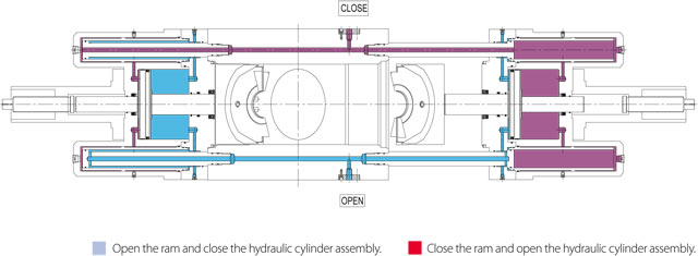
- Floating sealing is applied to the cylinder cover and the open/close of the cover by hydraulic power, so changing rams is quick and convenient.
- Auxiliary oil cylinder means a smaller volume with the same functionality.
- Ram rubber has significant storage volume, and adopts self-contained sealing.
- Standard configuration includes a manual locking device to ensure the ram is closed tightly in the case of hydraulic pressure loss
- Both manual and hydraulic locking device and the auxiliary oil cylinder can be installed into different positions according to your requirements, and installation positions changed easily.
- Ram cavity can be fitted with ram assembly of same type BOP made elsewhere.
|
TYPE U BOP operation data and needed oil quantity
|
|||||
|---|---|---|---|---|---|
| Drift diameter/pressure | Oil quantity for opening the ram (L/set) | Oil quantity for closing the ram (L/set) | Circle number of locking shaft | Closing ratio | Opening ratio |
| 7 1/16″/All pressure | 4.6 | 4.6 | 18 | 6.9:1 | 2.2:1 |
| 11″/the pressure except 15000psi | 10.6 | 11 | 30 | 7.3:1 | 2.5:1 |
| 11″/15000psi | 21.6 | 21.9 | 31 | 9.8:1 | 2.2:1 |
| 13 5/8″/the pressure except | 20 | 21 | 37 | 7.0:1 | 2.3:1 |
| 5/8″/15000psi | 39.4 | 40.2 | 45 | 10.6:1 | 3.6:1 |
| 20 3/4″/3000psi | 16.7 | 17.7 | 48 | 7.0:1 | 1.3:1 |
| 21 1/4″/2000psi | 16.7 | 17.7 | 48 | 7.0:1 | 1.3:1 |
| Shear ram chamber operation data and needed oil quantity | |||||
| Drift diameter/pressure | Oil quantity for opening the ram (L/set) | Oil quantity for closing the ram (L/set) | Circle number of locking shaft | Closing ratio | Opening ratio |
| 7 1/16″/All pressure | – | – | – | – | – |
| 11″/the pressure except 15000psi | 25.8 | 26.5 | 30 | 12:1 | 4.8:1 |
| 11″/15000psi | 33.7 | 34.1 | 31 | 15.2:1 | 3.7:1 |
| 13 5/8″/the pressure except | 39.8 | 41.3 | 37 | 10.8:1 | 4.5:1 |
| 13 5/8″/15000psi | 60.6 | 61.4 | 45 | 16.2:1 | 6:1 |
| 20 3/4″/3000psi | 54.2 | 56.4 | 48 | 10.4:1 | 4.4:1 |
| 21 1/4″/2000psi | 54.2 | 56.4 | 48 | 10.4:1 | 4.4:1 |
The weight in the above table is based on upper and lower flange form.
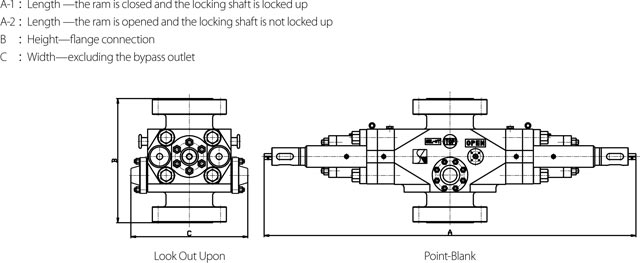
TYPE U SINGLE RAM BOP

Dimension Schematic of TYPE U Single Ram BOP
| Size (in.) | Working pressure(psi) | Vertical Path(in.) | A-1 (mm) | A-2 (mm) | B (mm) | C (mm) | Weight (Kg) |
|---|---|---|---|---|---|---|---|
| 7 1/16 | 3,000 | 7 1/16 | 1880 | 2780 | 611 | 515 | 1400 |
| 7 1/16 | 5,000 | 7 1/16 | 1880 | 2780 | 699 | 515 | 1500 |
| 7 1/16 | 10,000 | 7 1/16 | 2487 | 3363 | 1216 | 757 | 2150 |
| 7 1/16 | 15,000 | 7 1/16 | 2477 | 3273 | 832 | 768.8 | 2120 |
| 11 | 3,000 | 11 | 3105 | 4165 | 750 | 640 | 2406 |
| 11 | 5,000 | 11 | 3105 | 4165 | 898 | 648 | 4200 |
| 11 | 10,000 | 11 | 3200 | 4250 | 910 | 655 | 4300 |
| 11 | 15,000 | 11 | 3325 | 4413 | 1205 | 820 | 6725 |
| 13 5/8 | 3,000 | 13 5/8 | 3200 | 4356 | 795 | 743 | 3260 |
| 13 5/8 | 5,000 | 13 5/8 | 3627 | 4895 | 982 | 840 | 6540 |
| 13 5/8 | 10,000 | 13 5/8 | 3768 | 5046 | 1135 | 850 | 6640 |
| 13 5/8 | 15,000 | 13 5/8 | 3530 | 5460 | 1360 | 1000 | 10800 |
| 20 3/4 | 3,000 | 20 3/4 | 4120 | 5800 | 1030 | 1120 | 8100 |
| 21 1/4 | 3,000 | 21 1/4 | 4120 | 5800 | 940 | 1110 | 7600 |
The weight in the above table is based on upper and lower flange form.
TYPE U BOP Explosion Drawing

No. of Part Drawing of TYPE U Ram BOP
| No. | Name | Qty. Single Ram | Qty. Double Ram | 7 1/16″-15000psi | 11″-5000psi | 13 5/8″-5000psi |
|---|---|---|---|---|---|---|
| 1 | Ram guide rod | 4 | 8 | 2C07.15 | 2C06.10 | 2C02.15 |
| 2 | O-seal ring(spacer flange) | 2 | 4 | GB3452.1-1992 | 2C01.40 | 2C02.24 |
| 3 | Reinforced seal ring | 2 | 4 | 2C07.25 | 2C01.42 | 2C02.25 |
| 4 | Tightened seal ring | 2 | 4 | 2C07.26 | 2C01.41 | 2C02.26 |
| 5 | Gasket | 8 | 16 | 2C07.28 | 2C06.20 | – |
| 6 | Front rod seal ring of the main piston | 2 | 4 | 2C07.27 | 2C06.18 | 2C02.27 |
| 7 | Gasket | 2 | 4 | 2C07.18 | 2C06.12 | 2C02.18 |
| 8 | Retainer ring | 2 | 4 | GB/T893.1-1986 | GB/T893.1-1986 | 2C02.17 |
| 9 | Flange sealing assembly | 2 | 4 | 2C08.07.00 | 2C06.19.00 | 2C03.07 |
| 10 | Gate assembly | 2 | 4 | 2C07.01().00 | 2C06.08().00 | 2C02.01().00 |
| 11 | Shell | 1 | 1 | C08.02A.()() | C06.02A.()() | C03.02A.()() |
| 12 | O-SEAL RING(nozzle flange) | 2 | 4 | GB3452.1-1992 | GB3452.1-1992 | GB3452.1-1992 |
| 13 | Nozzle flange | 2 | 4 | 2C05.09 | 2C05.09 | 2C01.25 |
| 14 | Screw | 8 | 16 | GB/T70.1-2000 | GB/T70.1-2000 | 2C01.26 |
| 15 | Z1” external hexagon plug | 4 | 8 | 2C01.21 | 2C01.21 | 2C01.21 |
| 16 | Locking screw | 2 | 4 | 2C07.09 | 2C06.01 | 2C01.11 |
| 17 | Locking shaft seat | 2 | 4 | 2C07.06-01 | 2C06.03.00 | 2C03.06 |
| 18 | Nut | 16 | 32 | – | – | 2C01.14 |
| 19 | Bolt | 16 | 32 | GB/T70.1-2000 | GB/T70.1-2000 | 2C01.13 |
| 20 | Cylinder cap screw | 8 | 16 | 2C08.16 | 2C06.05 | 2C03.16 |
| 21 | Z1” inner hexagon screw plug | 4 | 8 | 2C01.34 | 2C01.34 | 2C01.34 |
| 22 | Sealing plug | 2 | 4 | 2C05.04 | 2C05.04 | 2C01.15 |
| 23 | Sealing gland | 2 | 4 | 2C05.05 | 2C05.05 | 2C01.16 |
| 24 | Large hydraulic cylinder | 2 | 4 | 2C08.12 | 2C06.04 | 2C03.12A |
| 25 | Z1/2” inner hexagon screw plug | 8 | 16 | 2C01.36 | 2C01.36 | 2C01.36 |
| 26 | Forged lifting lug bolt | 2 | 2 | GB/T 825-1988 | GB/T 825-1988 | ANSI/ASME B18.15 1985 |
| 27 | O-SEAL RING(large hydraulic cylinder) | 6 | 12 | GB3452.1-1992 | GB3452.1-1992 | GB3452.1-1992 |
| 28 | Gate change hydraulic cylinder | 4 | 8 | 2C08.20 | 2C06.14 | 2C02.20 |
| 29 | O-SEAL RING (replace hydraulic cylinder /large hydraulic cylinder) |
4 | 8 | GB3452.1-1992 | GB3452.1-1992 | GB3452.1-1992 |
| 30 | O-SEAL RING (replace hydraulic cylinder/spacer flange) | 4 | 8 | GB3452.1-1992 | GB3452.1-1992 | GB3452.1-1992 |
| 31 | Gate opening piston | 2 | 4 | 2C07.21 | 2C06.15 | 2C03.21 |
| 32 | O-SEAL RING(switch piston/shell) | 4 | 8 | GB3452.1-1992 | GB3452.1-1992 | GB3452.1-1992 |
| 33 | O-SEAL RING(switch piston) | 4 | 8 | GB3452.1-1992 | GB3452.1-1992 | GB3452.1-1992 |
| 34 | Guiding ring | 4 | 8 | – | 2C01.45 | 2C02.29 |
| 35 | Cock 1-8UNC | 2 | 4 | 2C01.20 | 2C01.20 | 2C01.20 |
| 36 | Secondary sealing grease | 2 | 4 | EM-09-L/25mm | EM-09-L/25mm | EM-09-L/25mm |
| 37 | Non-return valve | 2 | 4 | 2C01.07 | 2C01.07 | 2C01.07 |
| 38 | Intermediate flange | 2 | 4 | 2C08.13 | 2C06.06 | 2C03.13 |
| 39 | Intermediate flange screw | 24 | 48 | 2C08.19 | 2C06.13 | 2C03.19 |
| 40 | Z1/2” inner hexagon perforated screw plug | 2 | 4 | 2C01.32 | 2C01.32 | 2C01.32 |
| 41 | O-SEAL RING (large hydraulic cylinder/spacer flange) | 2 | 4 | GB3452.1-1992 | GB3452.1-1992 | GB3452.1-1992 |
| 42 | Gate closing piston | 2 | 4 | 2C07.22 | 2C06.16 | 2C03.22 |
| 43 | Main piston | 2 | 4 | 2C08.11.00 | 2C06.09.01 | 2C03.11 |
| 44 | Lip type seal ring of the main piston | 2 | 4 | 2C07.08-01 | 2C01.08 | 2C03.11A |
| 45 | Wearing ring of the main piston | 2 | 4 | 2C07.30 | 2C01.48 | 2C02.08 |
| 46 | Tail rod seal ring of the main piston | 2 | 4 | 2C07.27 | 2C01.49 | 2C02.30 |


Reviews
There are no reviews yet.